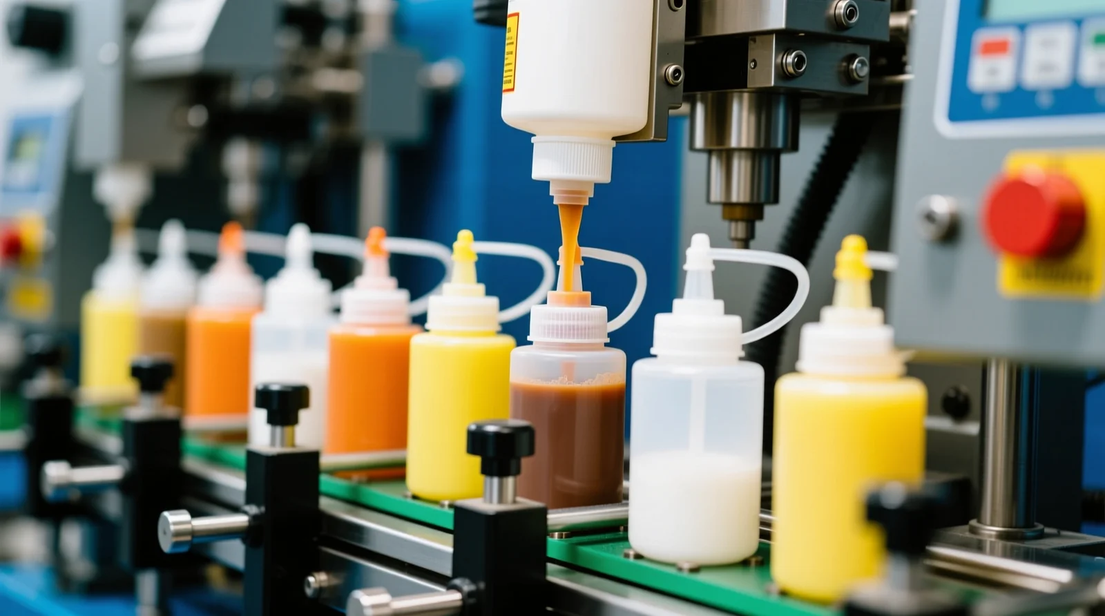
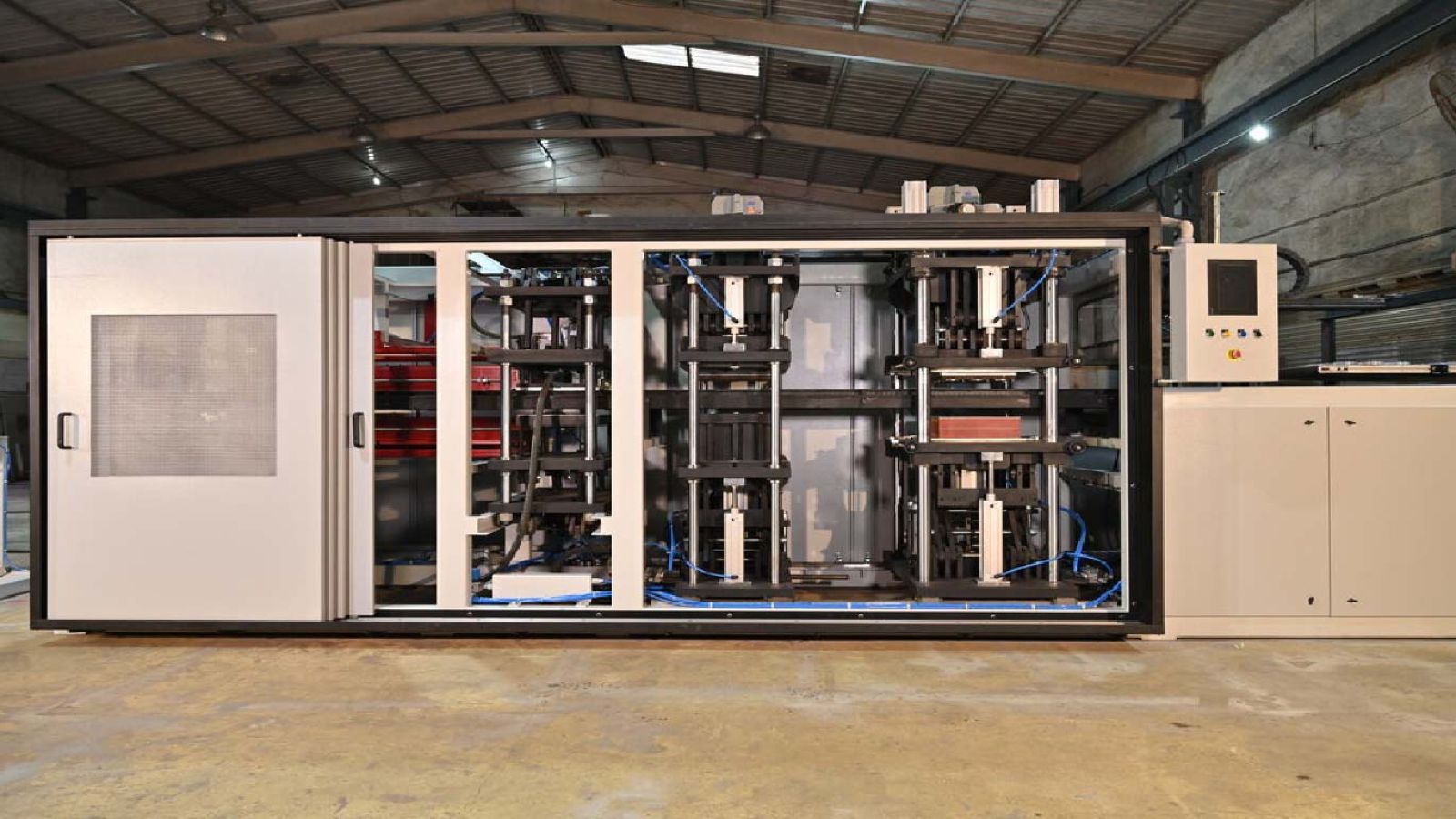
The core idea of this page: a tray sealer welds a lidding film onto a rigid preformed tray in a sealing station — and the value is in what happens in that station: MAP gas flushing, vacuum or skin packaging. Choose the sealer by the sealing format (MAP, vacuum-skin or seal-only) and the tray/film you actually run, then force a witnessed seal.
For the machine landscape, see Top 5 Tray Sealers Compared and Top 10 Sealing Machine Manufacturers.
How a tray sealer works
Tray infeed and sealing station
Filled trays are fed into the machine, and each tray is positioned under a sealing head. The lidding film is drawn over the tray, and the head presses a heated seal plate onto the tray flange, welding the film to the tray rim.
MAP, vacuum and skin formats
A MAP sealer flushes the tray headspace with a protective gas before sealing, a vacuum-skin sealer evacuates the air and draws the heated film down over the product, and a seal-only sealer just welds the lid. The format is chosen by the product and shelf-life target.
Cutting and discharge
After sealing, the film is cut around the tray, and the sealed tray is discharged. The tooling — the tray cavity and seal plate — is specific to the tray size, which is why format changeover and tool cost matter.
Failure modes to design around
- Seal leaks. A weak or wrinkled seal on the tray flange leaks the pack — the most common tray-sealer failure. Seal integrity must be verified on your tray and film.
- Tooling mismatch. A tray that does not match the tooling seals poorly or jams. Confirm the tray dimensions and flange tolerance.
- Residual oxygen. For MAP trays, a leaking seal or a poor gas flush raises residual O2 and shortens shelf life.
- Changeover time. Tray size changeover involves tooling swaps; on many SKUs the changeover time is a real cost.
How to verify a tray sealer
- Seal-integrity test: run a leak or burst test on sealed trays.
- Residual-oxygen check: for MAP trays, measure O2 inside the pack.
- Witnessed run: run your tray and film through the machine at production speed.
- Changeover: time a full tray-size changeover.
Frequently asked questions
Can a tray sealer do MAP and vacuum-skin?
Many automatic tray sealers support both MAP and skin formats, but the machine must be configured for it — confirm the sealing station and gas/vacuum options.
What is the difference between a tray sealer and a vacuum chamber?
A tray sealer welds film onto a rigid tray; a vacuum chamber seals a flexible pouch. They are different machines for different pack formats.
Why does tooling cost so much?
The tray cavity and seal plate are machined to the tray size, so each format has its own tooling — price it when comparing multi-format projects.
Related guides
- Sealing Machines: Top 10 Tray Sealers Compared (2026) — Five automatic tray sealers compared across sealing capability, format…
- Tray Sealing vs Vacuum Chamber Sealing: Which Closure Fits Your Pack — Tray sealing and vacuum chamber sealing solve different closure proble…
- Heat Sealing vs Induction Sealing: Closing Methods Compared — Heat sealing welds film with heated elements; induction sealing welds …
- MAP vs Vacuum Skin Packaging: Sealing for Shelf Life — MAP gas-flushes a tray headspace; vacuum skin packaging draws the film…
- Modified Atmosphere Packaging (MAP): Gases, Sealing and Shelf Life — modified atmosphere packaging (MAP) extends shelf life by replacing th…
- How Induction Sealing Works: Cap Liners and Heat Generation — induction sealing welds a foil liner inside a bottle cap by generating…
- Top 10 Sealing & Tray Sealing Machine Manufacturers Global (2026 Edition) — An independent ranking of the top global sealing machine manufacturers…
- Top 10 China Sealing Machine Manufacturers (2026) — An independent ranking of Chinese sealing machine builders across band…
Last verified: September 10, 2026.