
Introduction

Coherix will host a two-day open house at its expanded Ann Arbor, Michigan Innovation Centre (North American headquarters) focused on in-line adhesive bead inspection, automotive sealant quality control, and closed-loop robotic dispensing. The sessions are aimed at manufacturing and quality teams who need to verify bead geometry in real time (not after the fact), understand why defects happen, and see how inspection data can be used to adjust dispensing parameters on the line.
While the event includes live demos, the underlying topics—3D metrology (3D measurement), statistical process control, and machine-learning-based anomaly detection—remain relevant beyond the open house for teams evaluating upgrades from manual checks or 2D vision to 3D, quantitative bead measurement.
TL;DR: A technical open house in Ann Arbor covering 3D, in-line bead measurement and how those measurements can be used to correct adhesive/sealant dispensing variation in production.
Open House Dates, Format, and Audience (Ann Arbor, 2026)
The open house runs across Thursday–Friday, April 9–10, 2026, delivered as three half-day sessions at the Ann Arbor Innovation Centre.
Each session is designed for:
- Manufacturing engineers (process, equipment, launch)
- Quality engineers and metrology/inspection leaders
- Automation and robotics specialists (controls, integration)
- OEMs, Tier suppliers, and system integrators
Sessions combine short technical talks, live cell demonstrations, and Q&A time for application-specific discussion (materials, nozzle types, robot paths, measurement acceptance criteria, and data interfaces).
TL;DR: April 9–10, 2026 in Ann Arbor; half-day sessions built for engineers who own dispensing, inspection, or automation performance.
What Attendees Will Experience: Live In-Line Adhesive Bead Inspection Workflows
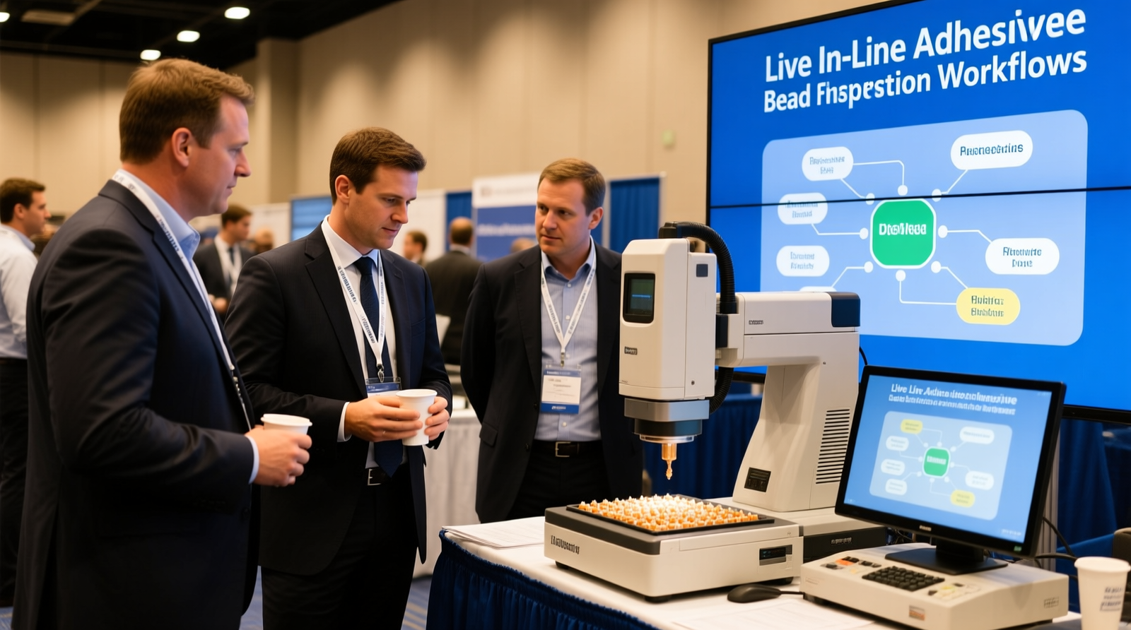
Each open house session includes:
- Luncheon discussions with application engineers and peers
- Live demonstrations of 3D bead measurement and feedback-driven process adjustment
- Technical presentations on dispensing variability, acceptance windows, and measurement set-up
- Q&A focused on real production constraints (cycle time, changeovers, traceability)
Attendees can bring their own problem statements (for example: “random bead skips on a door hem-flange station,” “battery lid seal squeeze-out,” or “pump drift over a shift”) and discuss how those issues show up in 3D measurement data and what corrective actions typically work.
TL;DR: Live, engineering-focused demos plus time to map your defect modes to measurable 3D bead features and corrective actions.
From Traditional Inspection to Closed-Loop Process Control in Adhesive Dispensing
Many plants still rely on a mix of manual checks (visual inspection, weigh checks, cut-and-measure) and 2D vision. These methods can be useful for presence/absence or gross positioning, but they often struggle to quantify bead height and cross-sectional area—two variables strongly tied to sealing and bonding performance.
In contrast, closed-loop process control means using measurement feedback to automatically correct the process. In dispensing, this generally involves three layers:
- Measurement layer: 3D sensing of bead width, height, position, and continuity
- Decision layer: rules + analytics to determine if the bead is trending out of tolerance
- Actuation layer: adjusting a controllable input such as flow rate, pump speed, dispense pressure, robot speed override, or path offset
For industry context on feedback control concepts and why measurement latency matters, see the overview of process control fundamentals from the International Society of Automation (ISA).
TL;DR: Closed-loop dispensing uses 3D bead measurements to trigger corrective actions (not just alarms), improving stability compared with manual checks or 2D-only presence detection.
3D Adhesive Bead Inspection and Adaptive Process Control Solutions for Automotive and EV Manufacturing
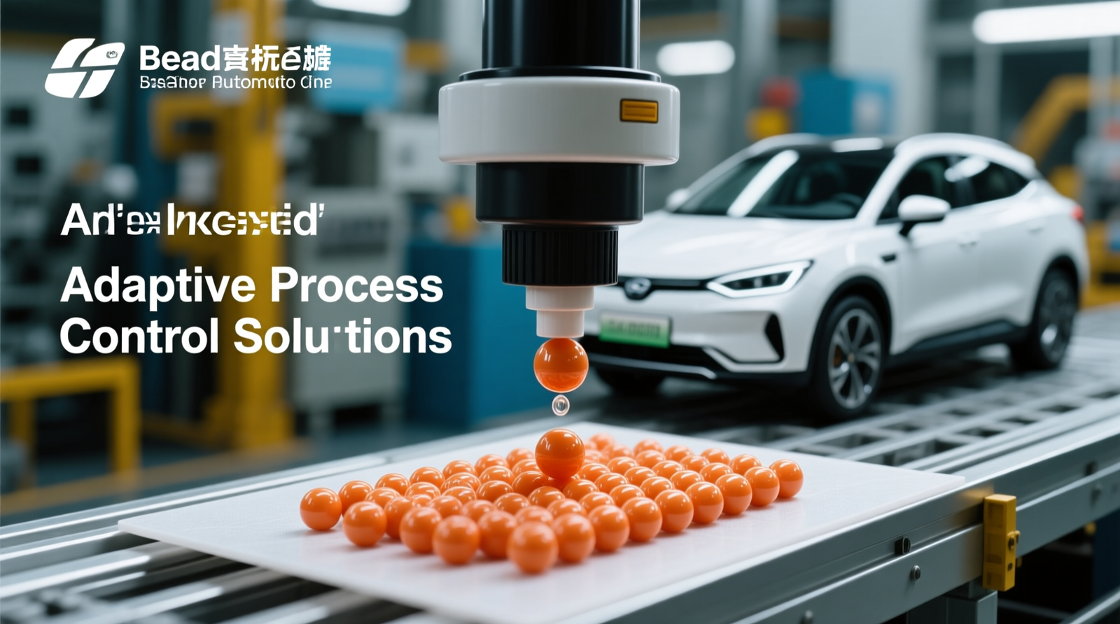
“3D inspection” can mean different technologies. In dispensing, common approaches include laser triangulation (a laser line viewed by a camera to reconstruct a height profile) and other structured-light methods. Laser triangulation is widely used for in-line metrology because it can produce dense profile data at production speeds when properly mounted and synchronized to robot motion.
Key technical capabilities typically evaluated for automotive sealant quality control include:
- Supported bead geometries: round beads, triangular/flattened beads, fillet beads, and gasket-style laydowns; also bead-on-flange and groove fills (where line-of-sight and reflectivity must be managed)
- Measured features: width, height, area (proxy for volume per unit length), bead centerline position, edge distance to datum, continuity (skip detection), and spatter/squeeze-out signatures
- Cycle-time fit: in-line inspection can be executed as continuous scanning along the bead path, or as sampling at critical segments (corners, joints, start/stop zones) when takt time is tight
- Accuracy and repeatability considerations: practical performance depends on sensor standoff, surface reflectivity, robot path stability, and calibration; evaluation should include gage R&R (repeatability and reproducibility) on representative parts and lighting/material conditions
For readers new to measurement system qualification, the AIAG (Automotive Industry Action Group) reference manuals are commonly used in automotive supplier environments; an overview of AIAG resources is available at aiag.org.
Example EV application scenario (anonymized): A battery pack lid sealing station experienced intermittent leaks traced to corner underfill and start/stop tapering. 3D bead profiles showed bead height dropping below the minimum threshold in the last 20–40 mm of the path during pump deceleration. A corrected recipe applied a short, controlled speed/flow compensation at end-of-path, reducing leak-related rework and lowering end-of-line water test failures.
TL;DR: 3D in-line bead inspection is most valuable when it quantifies height/area and links those measurements to specific corrective actions (flow/speed/path compensation), especially for sealing-critical automotive and EV processes.
How Machine Learning Supports Trend Analysis and Anomaly Detection (What’s Learned and How It Updates)
In this context, machine learning (ML) refers to models that learn normal process behavior from data rather than relying only on fixed thresholds. Typical data inputs include:
- 3D bead measurements: width/height/area distributions by segment, corner, or feature
- Process signals: pump pressure, flow estimates, temperature, material batch/lot, robot speed, and dispense valve states (when available)
- Context labels: part number, station ID, nozzle ID, time since last maintenance, and shift/time-of-day
Common ML tasks used in dispensing quality control include:
- Trend analysis: detecting gradual drift (e.g., nozzle wear causing bead width to widen over several hours)
- Anomaly detection: flagging patterns that don’t match baseline behavior (e.g., sudden bead height collapse linked to air ingestion or partial clogging)
- Root-cause support: correlating defect signatures with upstream conditions (temperature changes, batch changeovers, pump cycles)
Parameter update cadence: in many production deployments, baseline models are updated on a schedule (e.g., daily/weekly) or by event (new material lot, nozzle change, robot program revision). The goal is to adapt to controlled changes while avoiding “learning” true defects as acceptable. A practical approach is to retrain or recalibrate only on verified good production windows and to version-control recipes/model parameters alongside the robot and dispense programs.
For a neutral reference on anomaly detection concepts in industrial settings, see NIST’s manufacturing and data resources at nist.gov/manufacturing.
TL;DR: ML is used to learn normal bead and process patterns, detect drift/anomalies earlier than fixed thresholds, and update baselines on controlled schedules tied to verified-good production and change events.
Defect Modes in Automated Dispensing: What 3D Inspection Usually Catches (and What It Doesn’t)
Dispensing variation is typically driven by interacting factors—material rheology (flow behavior), temperature, pump dynamics, nozzle wear, and robot motion. In-line 3D inspection is strongest at detecting geometric defects, including:
- Skips/gaps: missing bead segments from air bubbles, valve misfire, or programming errors
- Thin areas / underfill: insufficient height/area, often at corners or during acceleration/deceleration
- Excess / squeeze-out signatures: too much material leading to contamination or fit issues
- Misplacement: bead centerline shifted from the target datum due to fixture variation or TCP (tool center point) drift
Where 3D inspection may need complementary checks: chemistry-related issues (wrong mix ratio in 2K materials, cure inhibition, contamination) may not be visible purely as a geometry change until later. Many plants pair geometry inspection with process interlocks (material ID verification, mix ratio monitoring, temperature controls) depending on risk.
Example automotive scenario (anonymized): A body-in-white station saw sporadic “stringing” and bead height spikes that caused cosmetic clean-up. 3D profiles identified the spike signature correlated with nozzle temperature swings after short downtime events. Stabilizing nozzle heating and adding a restart routine reduced manual cleanup time and improved first-pass yield on the station.
TL;DR: 3D inspection excels at catching geometric defects (gaps, thin areas, excess, misplacement) but may require additional controls for chemistry/cure risks.
Concrete Outcomes: Typical KPIs, Implementation Timelines, and ROI Expectations
Actual results depend on the baseline process, but manufacturers often track these KPIs when deploying in-line adhesive bead inspection with feedback correction:
- Scrap and rework reduction: commonly targeted in the 10–30% range on dispensing-related defects when defects are currently found late (end-of-line) rather than immediately
- First-pass yield (FPY): improvements often come from reduced intermittent failures (e.g., leak tests) and fewer “stop-and-fix” events
- Manual inspection hours: reduction when inspection is moved from periodic checks to automated verification of every part or every critical segment
- Mean time to detect (MTTD): shorter detection windows reduce the “defect escape” population during drift events
Implementation timeline (typical): a proof-of-concept and gage study can often be completed in a few weeks when parts and process access are available; full line rollout commonly takes longer due to controls validation, recipe sign-off, and run-at-rate testing.
ROI: payback is usually evaluated from reduced scrap/rework, fewer warranty/leak-test escapes, and reduced labor for manual checks. Many plants target payback within a year for high-volume or high-cost assemblies, although low-volume cells may prioritize risk reduction and traceability over pure payback speed.
Standards and qualifications to ask about: In automotive environments, request details on measurement system validation (e.g., gage R&R), traceability/reporting requirements, and any OEM-specific qualification pathways your program requires. For functional safety or machinery integration, teams may reference general frameworks like ISO 13849 (machine safety-related control systems), depending on the architecture and scope.
TL;DR: Track scrap/rework, FPY, manual inspection hours, and detection time; pilots can be done in weeks, and ROI is often targeted inside 12 months for high-impact lines.
Implementation Considerations: Integration Steps, Compatibility, and IT/OT Requirements

For teams evaluating closed-loop robotic dispensing, the integration work typically falls into these buckets:
- Mechanical integration: sensor mounting (end-of-arm vs fixed), cable management, and maintaining standoff/angle for consistent readings
- Robot and dispenser compatibility: integration is usually feasible with major industrial robot brands and common metering/valve systems, but the key is data access—being able to read/write recipe parameters or apply speed/flow overrides safely
- Controls and interfaces: connectivity through standard industrial protocols (e.g., Ethernet/IP, PROFINET, OPC UA—OPC Unified Architecture) depending on the cell’s PLC (programmable logic controller) and plant standards
- Data and traceability: storing bead metrics by VIN/serial, station, and timestamp; aligning with MES (Manufacturing Execution System) or quality databases when required
- Measurement validation: calibration routines, golden part strategy, and change control (robot program changes, nozzle swaps, material lot changes)
A useful neutral reference for OPC UA and why it’s commonly used for IT/OT data exchange is the OPC Foundation: opcfoundation.org.
TL;DR: Plan for sensor mounting, PLC/robot interfaces (often via standard industrial protocols), traceability data flows (MES/QMS), and formal measurement validation/change control.
Inside the Expanded Ann Arbor Innovation Centre: What You Can Validate On-Site
The Ann Arbor Innovation Centre is set up to support application trials and integration discussions, including:
- Robotic demonstration cells for representative dispensing paths (straight runs, corners, start/stop zones)
- Engineering lab capability to discuss material behavior, sensor setup constraints, and data/reporting needs
- Training and collaboration areas for OEMs and integrators reviewing acceptance criteria and rollout plans
If you cannot attend on the event dates, ask about follow-up options such as scheduled demos, evaluation visits, or limited-scope feasibility trials; the technical learnings (measurement strategy, defect signatures, integration approach) are applicable year-round.
TL;DR: The Innovation Centre supports hands-on validation of bead measurement, defect signatures, and integration concepts—and can remain a resource after the event.
How to Prepare (Even If You Can’t Attend): What to Bring and Who to Involve

To make the discussion productive, come prepared with:
- Part and process details: bead target width/height/area, takt time, and critical leak/bond requirements
- Top defect modes: examples such as corner underfill, intermittent skips, squeeze-out, bead misplacement, or leak-test failures
- Current controls: what you measure today (2D checks, manual audits, pump feedback), and where escapes occur
- Data availability: whether you can access robot speeds, pump parameters, temperatures, and part traceability IDs
Involve internal stakeholders early:
- Process engineering (recipes and acceptance criteria)
- Controls/automation (PLC/robot interfaces, networking)
- Quality/metrology (gage validation, audit strategy)
- IT/OT security (network segmentation, data retention)
- Operations/maintenance (nozzle/pump maintenance intervals, uptime constraints)
TL;DR: Bring bead specs, defect examples, takt-time constraints, and available signals; involve process, controls, quality, IT/OT, and maintenance to avoid surprises in rollout.
Next Steps and Call to Action
To attend the open house (April 9–10, 2026, Ann Arbor, MI), request registration details directly from Coherix via the company website: https://www.coherix.com/. If you’re evaluating a specific application (e.g., battery pack sealing, body-in-white seam sealing, glass bonding, or thermal interface material dispensing), ask about bringing sample parts or scheduling a separate technical review for your line constraints (cycle time, robot path access, and acceptance windows).
TL;DR: Use the Coherix website to request registration or a follow-up demo; come with a defined defect mode and bead spec so the discussion can be quantified.
FAQ

Q: What is in-line adhesive bead inspection, and how is it different from 2D vision checks?
A: In-line adhesive bead inspection measures the bead on the production line and typically quantifies 3D geometry rather than just appearance.
- 2D vision is often strong for presence/absence and gross position.
- 3D inspection can measure bead height, width, and derived area (a proxy for volume per unit length).
- This helps detect defects like corner underfill or thin bead height that may not be obvious in 2D.
Q: What 3D sensor technologies are commonly used for adhesive and sealant bead measurement?
A: Common 3D approaches include:
- Laser triangulation (laser line + camera) for profile scanning along the bead path
- Structured light methods for capturing 3D shape under controlled lighting
A: The best choice depends on standoff, reflectivity, field of view, and cycle-time constraints.
Q: How does machine learning help with closed-loop robotic dispensing in real production?
A: ML models typically learn from historical “good” runs and ongoing production data to:
- Detect drift (slow changes like nozzle wear)
- Flag anomalies (sudden deviations like partial clogs or air ingestion)
- Prioritize intervention by identifying which stations/segments are trending toward failure
A: Updates are usually scheduled (daily/weekly) or triggered by events (material lot changes, nozzle swaps), with controls to avoid learning defects as normal.
Q: What are typical defect modes in automotive sealant quality control, and what actions usually fix them?
A: Common defect modes and typical corrective actions include:
- Skips/gaps: check valve actuation timing, air in material, nozzle clogging; add restart routines
- Corner underfill: tune speed/flow compensation during acceleration/deceleration; verify robot path smoothing
- Misplacement: verify fixturing repeatability, re-teach TCP, and validate datum alignment
- Excess/squeeze-out: adjust flow/pressure, review stand-off, and confirm material temperature control
Q: What should I ask during a demo if I’m evaluating a system for EV battery sealing or body-in-white sealing?
A: Ask questions that map directly to your acceptance criteria and constraints:
- Measurement performance: expected repeatability on your surface/material and a plan for gage R&R
- Cycle-time impact: continuous scan vs segment sampling and how corners/start-stops are handled
- Interfaces: PLC/robot protocol support (e.g., OPC UA, PROFINET, Ethernet/IP) and recipe/change control
- Traceability: what bead metrics are stored per part and how data exports integrate with MES/QMS