Introduction

Correctly matching a hydraulic breaker (also called a hydraulic hammer) to an excavator or other carrier is critical for productivity, safety, and long-term equipment life. When breaker size, hydraulic flow, pressure, and carrier weight are out of balance, you risk overheating, premature wear, and costly downtime.
This guide explains how to match a breaker to a carrier using practical rules of thumb, quantified reference ranges commonly published by major breaker OEMs (original equipment manufacturers), and field-friendly selection and troubleshooting steps.
TL;DR: Start with the application/material, then choose the tool, then pick a breaker class that fits carrier weight and auxiliary hydraulics (flow/pressure/backpressure), and confirm with an on-machine flow test.
Why Proper Breaker–Carrier Matching Matters
A hydraulic breaker is only as effective as the machine driving it. Breaker performance depends on the right combination of:
- Hydraulic flow and pressure (from the auxiliary hydraulics circuit)
- Carrier weight and stability (operating weight, lift chart limits, and counterweight)
- Boom geometry and coupler configuration (reach, offset, and mounting type)
- Material type and application (rock, concrete, trenching, demolition)
If any of these are mismatched, the breaker may not deliver rated impact energy. Worse, the excavator’s hydraulic system, boom, and attachment interface can suffer serious damage. Operator habits like blank firing (firing without the tool firmly loaded against material), prying, and side loading accelerate wear and can turn a “close enough” match into a failure.
For credibility and up-to-date specifications, always cross-check with OEM documentation and safety guidance. For example, OSHA’s construction equipment safety resources can help reinforce safe attachment use: https://www.osha.gov/construction.
TL;DR: Matching isn’t just “will it fit?”—hydraulics, stability, geometry, and operator technique all interact to determine performance and component life.
Hydraulic Flow, Pressure, and Backpressure (Aux Hydraulics Setup)
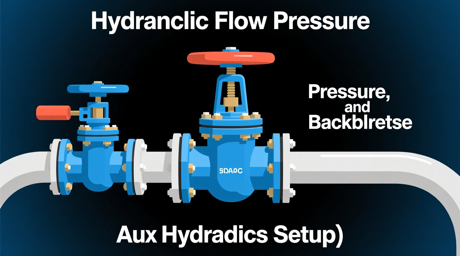
Hydraulic flow is the “volume” of oil delivered (commonly measured in GPM, gallons per minute). Pressure is the “force” (commonly psi, pounds per square inch). Both must stay within the breaker’s rated window at the auxiliary circuit—not just at the machine’s main system relief.
Flow (Breaker GPM Requirements)
- What it is: Oil volume feeding the breaker to cycle its piston and deliver blows.
- Why it matters: Exceeding rated flow “overdrives” the breaker—meaning you exceed its designed flow and impact frequency, which accelerates wear and heat. Too little flow causes weak blows and erratic firing.
- Typical reference ranges (industry common): Many breaker OEMs group breakers into energy/weight classes with defined flow windows. As a broad reference, breakers in the ~2,000–3,000 ft-lb impact-energy class are often paired with machines delivering roughly 25–45 GPM at the auxiliary circuit (exact values vary by OEM and model).
Pressure (Working Pressure vs. System Relief)
- System relief pressure: The maximum pressure the machine’s hydraulic system will allow before relieving (a protective limit).
- Working pressure at the auxiliary circuit: The pressure actually available at the breaker supply port under load, after losses through valves, plumbing, couplers, and hoses.
- Why it matters: A carrier may have high system relief pressure on paper, but the breaker may see lower working pressure due to restrictions—reducing impact energy and causing heat.
Backpressure (Return-Line Restriction)
- What it is: Pressure on the return line caused by restrictions returning oil to tank.
- Typical acceptable range (field reference): Many breaker OEMs target < 150–300 psi return-line backpressure under working conditions; some specify even lower. Excess return backpressure is a common cause of overheating and seal failures.
- Common causes: Undersized return hose, restrictive couplers, return oil routed through a spool instead of a dedicated free-flow return, clogged filters, or incorrect auxiliary plumbing.
Oil Temperature (Overheating Thresholds)
- Typical operating target: Keep hydraulic oil commonly around 120–160°F (50–70°C) during normal work when possible.
- “Too hot” warning band: Sustained temps above 180–200°F (82–93°C) often correlate with accelerated oil oxidation, seal hardening, and reduced lubrication film strength (exact thresholds depend on oil type and OEM guidance).
The “One-Pump-Flow” Rule (Conservative Guideline) + Exceptions
Joel Escalante, senior product specialist with Doosan Infracore North America, shares a field-proven rule of thumb: size the breaker so its maximum flow requirement does not exceed one pump’s flow capacity. Example: if an excavator is rated 2 × 50 GPM (total 100 GPM), choose a breaker that does not require more than ~50 GPM (or limit the flow with machine settings).
Important caveat: Some modern excavators can combine pump flow to the auxiliary circuit depending on control settings, priority valves, or “power/attachment modes.” That means “one pump only” is a conservative baseline, not a universal law. Larger demolition-class breakers on high-flow carriers may legitimately use combined flow—if the breaker is rated for it, the return line is free-flow, and oil cooling capacity is sufficient.
Always Verify with Real Flow Testing
Published specs are a starting point, but performance is determined by measured flow, working pressure, and backpressure at the couplers. For best results:
- Use a calibrated hydraulic flow meter to confirm actual GPM at the auxiliary circuit
- Record working pressure at the breaker supply under load (not just system relief)
- Measure return backpressure under working conditions
- Re-test after any change in couplers, hose lengths, adapters, or auxiliary valve settings
For background on hydraulic basics (flow vs. pressure), Bosch Rexroth’s learning resources are a helpful reference: https://www.boschrexroth.com/en/us/knowledge/.
TL;DR: Match GPM, working pressure, and return backpressure to the breaker’s ratings; keep oil temperature under control; treat “one pump flow” as a safe baseline—then confirm with a flow test.
Breaker Weight vs. Carrier Weight and Stability (Quantified Ranges)
Matching breaker weight to the carrier’s operating weight and lift capacity is just as important as hydraulic matching. The carrier must safely support the attachment through the full working envelope (including at reach) and maintain stability while delivering downforce.
Typical Breaker-to-Carrier Weight Ratio (Reference Range)
While every OEM publishes its own compatibility charts, a widely used reference range from multiple breaker manufacturers and dealers is:
- Breaker operating weight ≈ 7%–15% of the carrier’s operating weight for general breaking
- Up to ~18% may be seen in some heavy-duty applications with appropriate counterweighting, short-stick setups, and within lift chart limits
Use this only as a screening tool—always confirm against the breaker OEM’s excavator hammer compatibility chart and the carrier’s lift capacity.
Risks of a Breaker That Is Too Heavy
- Machine instability and tipping risk (especially at full reach or on slopes)
- Higher bending moments on boom/stick due to added mass and forward offset
- Accelerated pin, bushing, and structural fatigue from increased dynamic loads
- Overheating from sustained high-load operation and inefficient breaking technique
Risks of a Breaker That Is Too Small
- Low production and failure to fracture target material efficiently
- Overdriving risk if the carrier’s auxiliary flow is not reduced to breaker spec
- Operators compensating with excessive downforce, prying, or side loading (all damaging)
Warranty note: Many breaker warranties and service agreements require proof of correct setup (documented flow tests, proper hose sizing, and correct auxiliary settings). Keeping these records can prevent disputes later.
TL;DR: Use breaker weight as a % of carrier weight (often ~7%–15%) as a first-pass check—then confirm with lift charts and OEM compatibility tables.
Example Sizing Scenarios (Real Excavator Models + Breaker Classes)
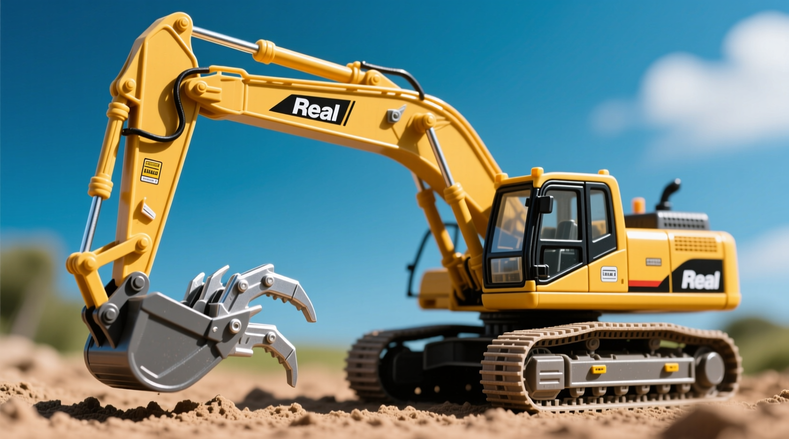
The exact breaker model varies by brand, but the sizing logic is consistent. Below are concrete examples using common excavator sizes and typical breaker classes. Always confirm using the breaker manufacturer’s model-specific sizing chart.
Scenario 1: Compact Excavator for Utility Trenching
- Carrier example: CAT 305.5E2 CR or Kubota U55 (roughly 5–6 ton class)
- Typical breaker class: ~250–500 lb breaker (compact class)
- Hydraulics target (typical): ~10–20 GPM auxiliary flow, moderate working pressure per OEM
- Use case: Sidewalk/demo, small footings, trench rock, light boulders
Scenario 2: 20-Ton Excavator for General Concrete and Rock Breaking
- Carrier example: CAT 320 / Komatsu PC210 / Volvo EC220 (20–22 ton class)
- Typical breaker class: ~1,800–3,000 lb breaker (mid-size class)
- Hydraulics target (typical): Often ~25–45 GPM for many breakers in the ~2,000–3,000 ft-lb impact-energy range (verify by OEM)
- Use case: Footings, slabs, ledge rock, scaling, moderate demolition
Scenario 3: 35–50 Ton Excavator for Heavy Rock or Primary Demolition
- Carrier example: CAT 336–349 class / Komatsu PC360–PC490 class
- Typical breaker class: ~4,000–8,000+ lb breaker (heavy class)
- Hydraulics target (typical): High-flow auxiliary setups; some carriers can supply combined pump flow depending on settings
- Use case: Large boulders, hard rock production breaking, heavy demolition
Tip: If you’re comparing options, search for your brand’s “hydraulic hammer sizing chart” and cross-reference the excavator model + serial range, because auxiliary hydraulics packages can differ even within the same model.
TL;DR: Use real carrier examples to sanity-check sizing: 5–6 ton machines typically run compact breakers, 20–22 ton machines run mid-size breakers, and 35–50 ton machines run heavy breakers—then confirm flow/pressure/backpressure by OEM chart and field test.
Boom Geometry, Couplers, and Mounting (Wear, Fatigue, and Offset)
Boom design and mounting setup directly affect how the breaker performs in the field. Even when flow and weight are correct, poor geometry can reduce productivity and increase wear.
Key Boom and Coupler Considerations
- Boom geometry: Long-reach and specialty booms change leverage and load distribution. They can reduce effective downforce at the tool and increase structural stress. Confirm the breaker is approved for your boom/stick configuration.
- Coupler forward offset: Quick couplers add weight and move the breaker farther from the stick pin. This increases the bending moment (torque) on the stick/boom, which can accelerate fatigue cracking and bushing wear—especially if operators pry or side load the tool.
- Hydraulic plumbing restrictions: Extra adapters, undersized couplers, or long hose runs can increase pressure drop and return backpressure, causing heat and reduced impact power.
- Pin-on vs. coupler mount: Pin-on often improves stiffness and reduces offset; couplers improve versatility. Choose based on the primary application and the carrier’s lift/geometry limits.
TL;DR: Geometry matters: couplers and long-reach setups increase leverage loads and restrictions—raising wear and lowering breaker efficiency if not accounted for.
Match the Tool Type to the Material and Application (Decision Framework)
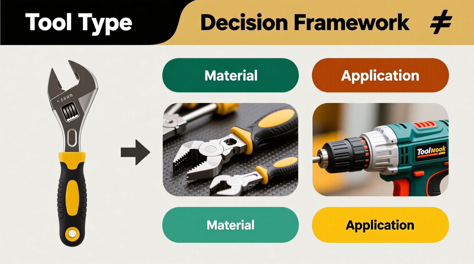
Material and job conditions should guide breaker selection. A simple, repeatable framework helps avoid mismatches:
- 1) Application/material: rock, reinforced concrete, asphalt, trenching, secondary breaking, scaling
- 2) Tool type: moil point, chisel, blunt (plus specialty tools depending on OEM)
- 3) Breaker size/class: based on carrier weight/stability and required impact energy
- 4) Hydraulic matching: breaker GPM requirements, working pressure, and allowable backpressure; confirm auxiliary hydraulics setup
Different Materials, Different Strategies
- Hard rock: Often benefits from higher impact energy and correct point geometry. Frequent repositioning and proper technique reduce blank firing.
- Soft or reinforced concrete: Often benefits from controlled line breaking with a chisel tool. Avoid prying and side loading, which can damage the tool and lower bushing.
- Trench work/utility: Smaller breakers can be faster and more precise around services—especially when matched to compact excavators or backhoes.
Selecting the Right Breaker Tool
- Moil/point: Hard rock, general breaking, scaling
- Chisel: Concrete, asphalt cuts, controlled demolition
- Blunt: Boulders, oversize reduction where shattering is preferred
TL;DR: Don’t start with breaker size—start with material and tool choice, then pick breaker class, then match hydraulics.
Carrier Types Beyond Standard Excavators (Mini Ex, Skid Steer, Backhoe)
“Carrier” can mean more than a conventional excavator. Matching rules still apply, but the constraints change.
Mini Excavators
- Often have limited cooling capacity and smaller return lines—watch oil temperature and backpressure closely.
- Auxiliary flow may be adjustable in-cab; verify settings on the monitor and document them for repeatability.
Skid Steers / Compact Track Loaders (CTLs)
- Hammer circuits may be standard-flow or high-flow; breaker GPM requirements must match the package.
- Return plumbing and case drain requirements (if applicable) are critical to prevent seal damage and heat.
Backhoe Loaders
- Hydraulics can be very capable, but auxiliary configurations vary widely by model and installed options.
- Stability can change dramatically with outriggers vs. wheels; follow safe positioning and lift/stability guidelines.
TL;DR: Minis are heat-sensitive, skid steers depend heavily on standard vs. high-flow packages, and backhoes vary a lot—so verify auxiliary hydraulics and return plumbing every time.
Step-by-Step Breaker Specification Process (Practical Selection Tool)
Use this stepwise process to specify a breaker you can actually run reliably—especially helpful if you’re comparing brands or building a bid package.
Step 1: Define the application and material.
Concrete thickness, reinforcement, rock type, desired production, trench width, and access constraints.
Step 2: Choose the tool type.
Moil/point, chisel, or blunt based on fracture mechanics and job constraints.
Step 3: Confirm carrier constraints.
Operating weight, lift chart at working radius, boom/stick configuration, and whether a coupler is used.
Step 4: Pick a breaker class by weight ratio + application.
As a starting screen, target breaker operating weight around ~7%–15% of carrier operating weight, then refine based on OEM charts and material hardness.
Step 5: Match hydraulics (the “hydraulic hammer sizing chart” step).
- Confirm breaker GPM range fits the carrier’s auxiliary flow capability (and the intended pump strategy).
- Confirm breaker pressure range matches auxiliary working pressure capability.
- Confirm allowable return backpressure can be met with your plumbing (often <150–300 psi as a general reference).
Step 6: Verify the auxiliary hydraulics setup on the machine.
Check in-cab attachment settings (flow, pressure/relief settings if adjustable, and attachment mode). Note that some machines allow combined pump flow depending on settings—consult the excavator OEM manual.
Step 7: Validate with a flow test and document results.
Record measured flow (GPM), working pressure at the auxiliary circuit, return backpressure, and oil temperature during a representative duty cycle. Keep records for warranty/service compliance.
TL;DR: Follow the steps: application → tool → carrier constraints → breaker class → hydraulic match → in-cab settings → flow test + documentation.
Common Misconfigurations (And How to Diagnose Them in the Field)
Many “bad breakers” are actually setup issues. Here are common misconfigurations tied directly to excavator hammer compatibility and auxiliary hydraulics setup.
- Flow set too high (overdriven): Breaker runs hot, rapid bushing/tool wear, harsh vibration, frequent seal leaks.
- Return line too restrictive: High backpressure, overheating, loss of power, premature seal failure.
- Wrong tool for material: Slow production, excessive blank firing, tool breakage, operator compensating with prying/side load.
- Incorrect nitrogen charge (gas-charged accumulators on some breakers): Weak blows, erratic firing, inconsistent impact energy.
- Couplers/adapters undersized: Pressure drop, heat, and reduced impact—especially noticeable under continuous breaking.
TL;DR: Most field problems trace back to flow too high, return restriction/backpressure, wrong tool choice, or gas charge and plumbing issues.
Troubleshooting Guide (Symptoms → Likely Causes)
Use the symptom-to-cause mapping below before you pull the breaker apart.
Overheating (oil temp rising fast; hoses/couplers too hot to touch)
- Likely causes: Flow set too high (overdriving = exceeding designed flow/impact frequency), excessive return backpressure, insufficient oil cooling capacity, restrictive couplers/hoses, continuous duty without breaks.
Weak blows / low production
- Likely causes: Flow too low, working pressure too low at auxiliary circuit (pressure drop), nitrogen charge low (if applicable), worn tool/bushings, incorrect tool type for material.
Erratic firing / “chattering” / intermittent impacts
- Likely causes: Flow instability, aeration/cavitation, incorrect auxiliary valve settings, tool not kept loaded (blank firing), hydraulic oil viscosity issues (too cold/too hot).
Excessive vibration, rapid tool/bushing wear
- Likely causes: Overdriving, prying/side loading, worn bushings, poor mounting fit, incorrect tool retention components, misaligned coupler mount increasing bending loads.
TL;DR: Match the symptom to hydraulics first (flow/backpressure/working pressure), then check tool choice, gas charge, wear parts, and operator technique.
Operating Guidance and Training Topics (Prevent Damage)
Correct setup only works if operators run the breaker correctly. Consider training that covers:
- How to verify flow settings on the in-cab monitor (attachment profiles, flow percentage, high-flow enable)
- How to recognize over- vs. under-driving: overdriven breakers run hot/harsh; under-driven breakers feel weak and may misfire
- Positioning technique by material: keep the tool perpendicular, maintain steady downforce, reposition frequently in hard rock to avoid blank firing
- Avoiding prying and side loading (major causes of tool and lower-bushing damage)
TL;DR: Train operators to confirm in-cab settings, keep the tool loaded and straight, and recognize heat/vibration as early warnings of mismatch.
Extreme Climate Notes (Cold Start vs. High Ambient Heat)

- Cold weather: Oil viscosity increases, which can reduce flow and cause sluggish operation or cavitation. Warm up hydraulics and consider OEM-approved cold-weather hydraulic oil grades.
- Hot weather: Oil thins, leakage increases, and cooling systems can be overwhelmed—raising oil temperature and accelerating wear. Monitor temperature and schedule duty cycles (breaks) as needed.
TL;DR: Cold oil can starve the breaker; hot ambient conditions can push oil temperature over safe limits—adjust warm-up, oil grade, and duty cycle accordingly.
Maintenance: Keeping the Hydraulic Hammer Alive
Even the best-matched breaker and carrier will fail early without proper maintenance. Consistent care protects your investment and keeps productivity high.
Core Breaker Maintenance Practices
- Daily lubrication: Follow OEM intervals for tool and bushing greasing, using the recommended grease type and quantity.
- Inspect tool and bushings: Check for wear, cracks, and abnormal scoring. Replace worn parts before they damage the housing.
- Monitor hydraulic oil: Keep oil clean, at proper viscosity, and within temperature limits. Replace filters on schedule.
- Check nitrogen charge (if applicable): Maintain correct charge pressure in gas-charged breakers to preserve impact energy.
- Hoses/couplers: Verify correct hose sizing and inspect for restrictions and heat-related degradation.
Following the manufacturer’s maintenance schedule and training operators on proper technique are key steps in extending the life of both the breaker and the carrier.
TL;DR: Grease, inspect wear parts, keep oil clean/cool, verify gas charge (if applicable), and maintain correct hoses/couplers.
Conclusion

Matching a hydraulic breaker to a carrier is about balance: hydraulics, weight/stability, geometry, tool-to-material fit, and operator technique. Use OEM charts and a conservative flow approach (often “one pump flow”), but remember modern excavators may allow combined flow depending on settings—so validate with real flow and pressure testing at the auxiliary circuit.
- Match hydraulics first: correct GPM, working pressure, and low return backpressure (then verify with a flow meter).
- Respect weight/stability and geometry: breaker weight ratios and coupler offset affect fatigue and safety.
- Optimize the job system: tool selection + operator technique + maintenance prevent heat, wear, and downtime.
TL;DR: Use OEM charts + measured flow/pressure/backpressure, size by stability and weight ratio, select the right tool for the material, and train operators to avoid blank firing and side loading.
FAQ
Q: Is there a reliable hydraulic hammer sizing chart for excavator hammer compatibility?
A: Yes—most breaker OEMs publish excavator-to-breaker compatibility charts listing acceptable carrier weight ranges and auxiliary hydraulics requirements (GPM/pressure). Use those charts first, then confirm your actual auxiliary flow, working pressure, and return backpressure with a flow test because couplers, hoses, and valve settings can change real performance.
Q: What breaker weight percentage should I target relative to my excavator’s operating weight?
A: As a practical screening range, many users target breaker operating weight around 7%–15% of the carrier’s operating weight for general work, then validate against lift charts and the breaker OEM’s recommendations. If you’re using a quick coupler or long-reach boom, be more conservative because forward offset increases bending loads and reduces stability.
Q: What hydraulic backpressure and oil temperature numbers should I watch when troubleshooting?
A: Many breaker OEMs aim for return-line backpressure below roughly 150–300 psi under load (check your breaker’s spec). For temperature, try to keep hydraulic oil around 120–160°F in normal conditions; sustained operation above ~180–200°F is a common warning zone for accelerated oil and seal degradation (exact limits depend on oil type and OEM guidance).
Q: How do I know if I’m overdriving a breaker (too much flow)?
A: Overdriving means exceeding the breaker’s designed flow and impact frequency. Common signs include rapid oil heating, harsher vibration, faster tool/bushing wear, and seal leaks. Verify by checking the in-cab auxiliary settings and measuring actual GPM with a flow meter at the couplers.
Q: Can I use combined pump flow to run a bigger breaker than the “one-pump-flow” rule suggests?
A: Sometimes. The one-pump-flow guideline is conservative and helps avoid overheating, but some modern excavators can route combined pump flow to the auxiliary circuit in certain modes. Only do this if the breaker is rated for the higher flow, the return is truly free-flow with acceptable backpressure, and oil cooling capacity is adequate—then document the setup for warranty and service requirements.